21/06/2012, 19:56
iLGambero ha scritto:
Ma un conto è un fenomeno sostanzialmente elettro-magnetico come può essere quello aurorale, altre cosa è quella spirale, che mi pare più un fenomino chimico-fisico, dove si vedere chiaramente un'espansione di un particolato dal centro verso l'esterno (tipo scia di condensa per intenderci)
Non vedo che attinenza ci sia tra i due fenomeni.
Tutto può essere, anche se vedere "chiaramente" un espansione di particolato, secondo me è soggettivo...
Io penso che se ti dicono ufficialmente che riescono a produrre effetti ottici rilevabili ad occhio nudo all'interno di un fenomeno naturale luminoso di per sè stesso, potrebbe essere credibile che riescano a creare (secondo me come effetto collaterale e non desiderato!) un effetto luminoso, di notte, come quella spirale...
21/06/2012, 20:00
Angeldark ha scritto:
Here we report observations of radio-induced optical emissions bright enough to be seen by the naked eye, and produced not in the quiet mid-latitude ionosphere, but in the midst of a pulsating natural aurora. This may open the door to visual applications of ionospheric heating technology or provide a way to probe the dynamics of the natural aurora and magnetosphere.
Fonte:http://www.nature.com/nature/journal/v433/n7025/full/nature03243.html
E cosa c'entrerebbe questo inciso sullo studio delle aurore boreali eccitate attraverso l'emissione di onde con la spirale norvegese? Siamo in contesti totalmente diversi, anche perchè non tieni conto che l'evento norvegese non è esclusivamente limitato all'osservazione della spirale apparsa improvvisamente nel cielo.
Continui a sforzarti nel far collimare a tutti i costi una ricerca scientifica sulle aurore boreali con ciò che avrebbe generato la spirale norvegese.
La cosa buffa è che incrociando questi studi sulle aurore boreali con la spirale norvegese si incappa ancora una volta in discussioni a matrice cospirazionista, come avvenuto anche in quest'altro forum:
http://www.conspiracy.co/forums/main-wa ... n-sun.html
Rendo l'idea di come viene strumentalizzata la cosa?
Sarà la quinta volta che te l'ho visto scrivere... oppure era l'altro tuo partner? Ora non lo ricordo... chiedo veniaAngeldark ha scritto:
E fino a quando verranno tollerati interventi offensivi e prese in giro senza adeguate misure di ammonimento pubblico, questo rimarrà il mio ultimo intervento nel forum!
Ultima modifica di _INSIDER_ il 21/06/2012, 20:01, modificato 1 volta in totale.
21/06/2012, 20:50
Angeldark ha scritto:Blissenobiarella ha scritto:Aztlan ha scritto:
...Ad altissima quota.
Ma qui la scia è a zig zag alla partenza dal terreno, a quota più bassa, e poi diventa regolare.
Come la mettiamo?
Continuate a non rispondere alla domanda....
Oddio...
Az quelle scie sono ad alta quota. Il modo in cui sono illuminate e rilucono non lascia spazio a dubbi. Se rilucono in quel modo infatti è perchè la radiazione solare le sta eccitando.
Guarda, ti ho linkato un sito di esperti di aeronautica, contattali e chiedi a loro, non so che altro dirti.
Non lascia spazio a dubbi...non ti ho mai visto ragionare così, ti preferivo quando una seppur minima riserva la mantenevi...
Per me il dubbio è sacrosanto. Ma bisogna anche essere capaci di riconoscere quello che si vede. Se vedo un cavallo non posso avere dubbi che si tratti di un cavallo.
Le ipotesi su Haarp e le tecnologie per la manipolazione della ionosfera e il geomagnetismo, sono interessanti e meritano di essere approfondite senza pregiudizio. Non credo che in questo caso il fenomeno osservato possa essere correlato a questa tecnologia nel modo in cui tu pretendi che lo sia.
Angel, non tiriamo in ballo adesso la scusa degli insulti.
Tutti avete contribuito a infiammare i toni di questa discussione cercando di mettere in ridicolo le tesi di un singolo utente.
A me non sta bene questo modo di comportarsi, lo trovo molto più offensivo e violento di un paragone con Cochi e Renato.
Facciamo dunque un po' di autocritica. Se non ci piace questo clima acido nelle nostre discussioni, non contribuiamo a crearlo.
21/06/2012, 21:40
"Quando il saggio indica il cielo lo stolto osserva il dito"
Il dito e la luna. Rappresentazioni mediali e costruzione sociale della realtà
«Quando il saggio indica la luna, lo stolto guarda il dito» recita un proverbio di discussa
origine. Il significato è chiaro: non bisogna fermarsi alla superficie delle cose, degli
eventi, ma coglierne la profondità, la verità.
meditate gente meditate![[;)]](./images/smilies/UF/icon_smile_wink.gif "Occhiolino")
Il dito e la luna. Rappresentazioni mediali e costruzione sociale della realtà
«Quando il saggio indica la luna, lo stolto guarda il dito» recita un proverbio di discussa
origine. Il significato è chiaro: non bisogna fermarsi alla superficie delle cose, degli
eventi, ma coglierne la profondità, la verità.
meditate gente meditate
21/06/2012, 21:52
E talvolta non solo non si vede la luna per fissare il dito, ma guardando il dito si dice : "Porca paletta! Una salsiccia volante!"
22/06/2012, 00:20
hahahahahaha......bella li...![[:o)]](./images/smilies/UF/icon_smile_clown.gif "Clown")
22/06/2012, 09:53
Blissenobiarella ha scritto:
...ma guardando il dito si dice : "Porca paletta! Una salsiccia volante!"
Avrei detto un sigariforme
![[:279]](./images/smilies/UF/279.GIF "Emoticon")
25/06/2012, 18:51
Scusate ma allora negate pure l' evidenza?
Esiste già ed è riconosciuto ufficialmente la tecnologia per produrre questo effetto della spirale luminosa nel cielo
proiettando energia nell' atmosfera usando installazioni a terra
ed è stata già usata da diversi anni proprio in quel luogo.
Continuamo a osservare fenomeni simili e voi cosa dite? Che è il solito missile? Ma allora... non volete vedere.
Cosa aveva detto il buon Aztlan? Proiezione di energia in atmosfera. La NASA conferma.
Comincio ad annoiarmi...
Aztlan
26/06/2012, 16:51
E'h, sì; a volte anch'io.![[8)]](./images/smilies/UF/icon_smile_shy.gif "Compiaciuto")
26/06/2012, 17:02
Aztlan ha scritto:
Continuamo a osservare fenomeni simili e voi cosa dite? Che è il solito missile? Ma allora... non volete vedere.
Ci vuole una bella fantasia per accostare questo fenomeno, che tanto ti sta a cuore, alla spirale norvegese. Stai insistendo su una versione che non regge rispetto a quanto fotografato, filmato e documentato sui cieli norvegesi. Quella non è energia in atmosfera, ma solo espulsione di materiale dal terzo stadio del missile.
Aztlan ha scritto:
Proiezione di energia in atmosfera. La NASA conferma.
Per l'appunto, non c'entra una mazza con la spirale norvegese.
26/06/2012, 17:15
Non è facile facile inviare energia in atmosfera. Serve una distribuzione di antenne su un territorio vastissimo,e una serie di segnali perfettamente in fase tra loro (una roba tipo Haarp).
Una sola antenna (tipo quella presente in Norvegia) non può assolutamente fare nulla,nè attivare un plasma ad altissime quote. Perchè nel momento esatto che 'spara',ionizzerebbe all'istante l'aria attigua dando vita a esplosioni identiche a quelle dei fulmini,autodanneggiando la propria struttura metallica.
Secondo problema.In certi momenti della giornata,poi,la ionosfera riflette completamente certe radioonde,con il risultato che una 'sparata' di energia verso l'alto può ritornare a terra e incenerire un passante.O far saltare in aria un distributore di benzina.O buttare giù un aeroplano.Il tutto a centinaia di km da dove è avvenuta la 'sparata'.
Mi sento di escludere che la parabolica presente in Norvegia possa aver creato quell'effetto a spirale,non per partito preso,quanto per la difficoltà tecnica di adoperare un puntatore da 900 MHz e innescare un plasma del diametro di km e km. Più facile che sia stata l'idrazina del razzo a creare un effetto a irradiazione fresnel,grazie ai tre volumi rotanti.Chiaramente,l'effetto fresnel originato dal sole non può essere stato investigato dai russi,in quanto non di loro specifica competenza e soprattutto non è nel loro interesse valutare come si comportano i raggi solari quando attraversano una spirale a tre bracci cilindrici.
26/06/2012, 19:54
IdentFlyObj ha scritto:
Non è facile facile inviare energia in atmosfera. Serve una distribuzione di antenne su un territorio vastissimo,e una serie di segnali perfettamente in fase tra loro (una roba tipo Haarp).
Una sola antenna (tipo quella presente in Norvegia) non può assolutamente fare nulla,nè attivare un plasma ad altissime quote.
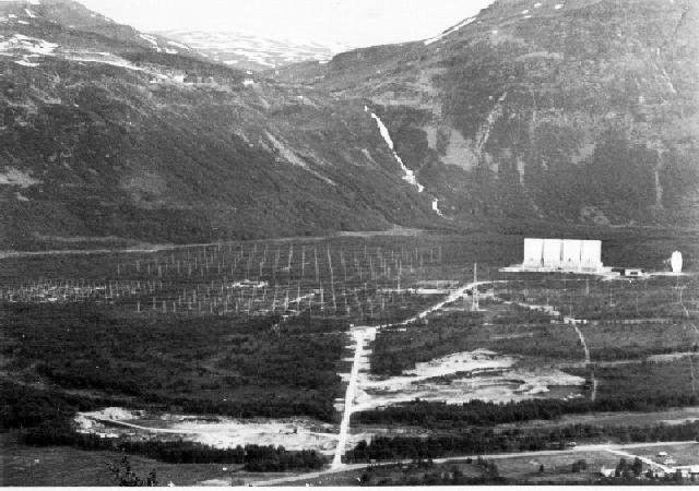
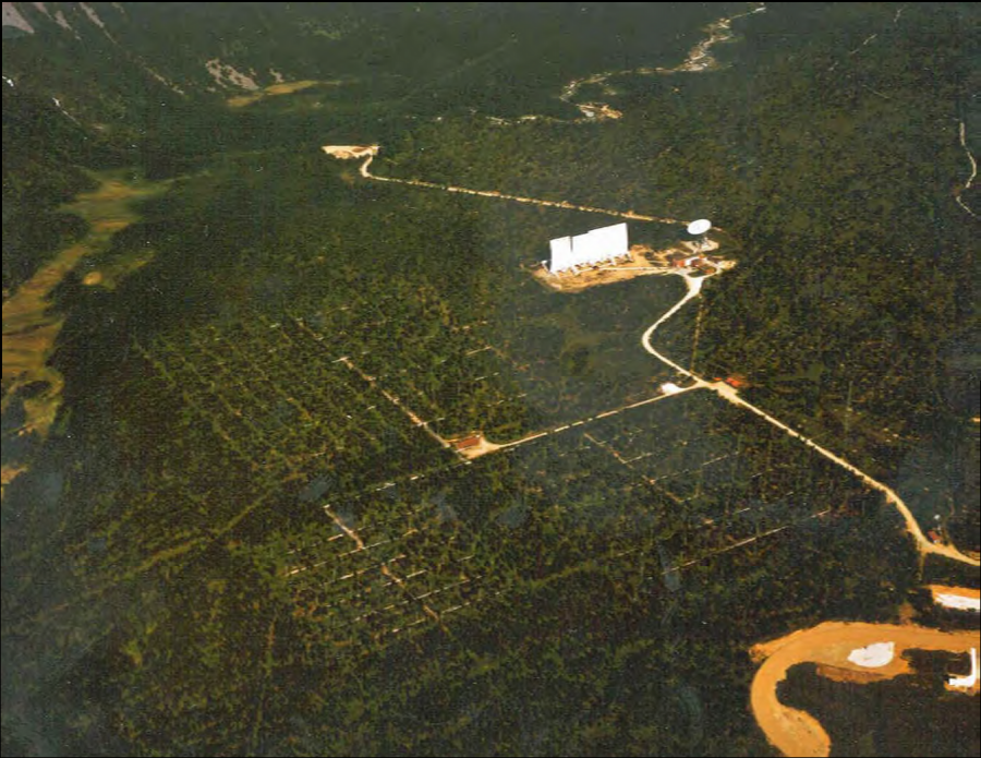
L'impianto Eiscat di Tromso E' una struttura HAARP!
E chi ti ha detto che c'è una sola antenna!

26/06/2012, 20:16
26/06/2012, 22:13
Quello definito 'heater', riscaldatore,è un semplice ammasso di ferracci.
Sono semplici tubi di alluminio,disposti a quadrato,che irradiano a dipolo.
Immagine:

87,12 KB
Se verificate il lobo d'irradiazione di un dipolo (per quanto ad array ossia multipli),vedrete che copre una porzione di cielo gigantesca con un fascio LINEARE.
La linea può spazzolare il cielo tra nord e sud,oppure tra est e ovest.
Ma quanto hanno fotografato e videoripreso in Norvegia non ha carattere assiale, bensì ha una generatrice a SPIRALE rotante.
Ora,l'unico tipo di antenna capace di irradiare a spirale,potrebbe essere l'antenna a parabola lì presente,il problema è che il plasma si forma prima su di essa,danneggiandola irreparabilmente.
Per cui,per poter affermare si tratti di un esperimento eseguito a Tromso,bisogna far sì che la spirale rotante abbia un'antenna rotante che l'abbia emessa. Nè quell' heater nè le parabole hanno questa possibilità.Non so quanto sia chiaro quanto esposto,è un problema di geometria emissiva,nonchè di potenze trasmesse ( Haarp è inifinitamente superiore a Eiscat)
Sono semplici tubi di alluminio,disposti a quadrato,che irradiano a dipolo.
Immagine:
87,12 KB
Se verificate il lobo d'irradiazione di un dipolo (per quanto ad array ossia multipli),vedrete che copre una porzione di cielo gigantesca con un fascio LINEARE.
La linea può spazzolare il cielo tra nord e sud,oppure tra est e ovest.
Ma quanto hanno fotografato e videoripreso in Norvegia non ha carattere assiale, bensì ha una generatrice a SPIRALE rotante.
Ora,l'unico tipo di antenna capace di irradiare a spirale,potrebbe essere l'antenna a parabola lì presente,il problema è che il plasma si forma prima su di essa,danneggiandola irreparabilmente.
Per cui,per poter affermare si tratti di un esperimento eseguito a Tromso,bisogna far sì che la spirale rotante abbia un'antenna rotante che l'abbia emessa. Nè quell' heater nè le parabole hanno questa possibilità.Non so quanto sia chiaro quanto esposto,è un problema di geometria emissiva,nonchè di potenze trasmesse ( Haarp è inifinitamente superiore a Eiscat)
27/06/2012, 01:13
IdentFlyObj ha scritto:
Ora,l'unico tipo di antenna capace di irradiare a spirale,potrebbe essere l'antenna a parabola lì presente,il problema è che il plasma si forma prima su di essa,danneggiandola irreparabilmente.
Nessuno ha mai detto che le emissioni di onde siano irradiate a spirale...è il plasma che, una volta creato nella ionosfera tramite riscaldamento da parte di onde elettromagnetiche, tende a disporsi in vortice con emissioni ottiche spiraleggianti visibili ad occhio nudo...
Le antenne a parabola operano nelle alte frequenze denominate UltraHighFrequency o frequenze radar e sono assolutamente inadatte ad operare sul plasma...
Il plasma risuona a frequenze estremamente basse denominate Extremely Low Frequency e per queste frequenze servono proprio quegli "ammassi di ferracci" come li chiami te...
Se non mi credi puoi leggerlo facilmente sul sito ufficiale dell'installazione Eiscat norvegese:
EISCAT's ionospheric Heating facility (including Dynasonde)
Document Actions
Description of the EISCAT heating facility
The Heating facility is situated next to the UHF and VHF incoherent scatter radars.
The Heater is used for ionospheric modification experiments applying high-power transmissions of high-frequency electro-magnetic waves to study plasma parameters in the ionosphere. The name Heating stems from the fact that these high power electromagnetic waves, which are transmitted into the ionosphre with high-gain antennas, heat the electrons and thus modify the plasma state. To create plasma turbulence, the transmitted frequencies have to be close to the plasma resonances, which are 4 to 8 MHz.
Technical Description:
Transmitters
12 linear class AB tetrode valve (or tube for you Americans) power amplifiers of 100 kW continuous rating each, driven by a 1.5 kW solid state wideband exciter. Minimum pulse length is about 20µS. Any frequency in the range 3.85-8 MHz can be tuned, but we have been allocated the following: 4.04, 4.544, 4.9128, 5.423, 6.2, 6.77, 6.96, 7.1, 7.953 MHz. The transmitters can be tuned up either uniformly or to different frequencies in 2 groups of 6, 3 groups of 4, 6 groups of 2, or 12 different frequencies.
Antennas
There is a choice of 3 arrays. Two of the arrays (numbers 2 and 3) have 6×6 crossed dipoles, resulting in 36 antennas. They cover the frequency range 3.85-5.65 MHz and 5.5-8 MHz. The gain of these is 24 dBi giving a half power beam width of 14.5 ° and a maximum effective radiated power of 300 MW. A pair of transmitters is fed to orthogonal antennas on a row of antennas. A third array (array 1), covering 5.5-8 MHz, has a gain of 30 dBi giving 1200 MW of effective radiated power. A pair of transmitters in this array feeds two rows of antennas. Each row has 12 crossed dipoles giving a total of 144 antennas. A particular transmitter can be connected to only one particular row (or pair of rows in array 1), but in any array independent of the other transmitters. The transmitters feed the antennas through about 50 km of aluminium co-axial transmission lines.
Control system
Tuning to a new frequency is done by a PC and can take a few minutes. Tilting of the beam in the north-south plane up to about ± 30 ° is possible. Power can be chosen in 2.5% steps of the maximum tuned power, which itself can be less than the maximum possible. Complicated amplitude modulation formats are possible under computer or other sources of control. For example a so-called "SOUSY-switch" is used for ON/OFF modulation by about 70dB. Modulati on frequencies in the range 15-200 Hz with duty cycles near 50% can not be used due to power supply resonance problems. The radiated wave can be linearly or circularly polarized with either sense of rotation. Polarization reversal can be achieved on a pulse to pulse basis. Accurate timing to within microseconds is possible. Frequency stability is as good as the EISCAT cesium beam reference.
Dynasonde
A digital HF sounder covering ca. 1-30 MHz is also available. This can be run like an ionosonde or in other modes such as fixed frequency soundings. Spaced receiving antennas are used. A sample ionogram shows a "clean" ionospheric trace.
Fonte:http://www.eiscat.com/about/info/heating/
Questi sono gli "ammassi di ferracci" nonchè "semplici tubi di alluminio" del riscaldatore di Tromso visti da vicino:
http://www.flickr.com/photos/51924909@N ... otostream/
Questi sono gli "ammassi di ferracci" del riscaldatore di Sura in Russia
(cliccare sulla foto per ingrandire!):

"Ammassi di ferracci" del riscaldatore dell' NMRF in India:
